8.7 - Type II Recovery Procedures
Module: Type II High and Very-High-Pressure Appliances
Technical and regulatory verification date: August 12, 2026
Primary current authority: Current 40 CFR § 82.156 and current EPA Section 608 Type II test-topic and service-practice guidance
Course role: Applies the general recovery principles from Module 5 to Type II appliances, emphasizing liquid-first recovery, vapor completion, temperature management, receiver and liquid-line access, oil minimization, pressure rebound, parallel-compressor isolation, and the current system-dependent-equipment charge limitation
Learning Objectives
After completing this section, a student should be able to:
- Explain why accessible bulk liquid is normally recovered before the remaining vapor when the appliance and recovery equipment permit.
- Describe the transition from liquid recovery to vapor recovery.
- Explain how cooling the recovery cylinder can reduce recovery-machine back pressure and why any cooling method must remain within cylinder and manufacturer limits.
- Explain how controlled appliance warming can increase refrigerant vapor pressure and speed final recovery.
- Select useful receiver and liquid-line access points without assuming that every receiver port contains liquid.
- Explain why vapor recovery tends to minimize lubricant carryover compared with aggressively moving liquid from oil-rich regions.
- Perform a pressure-rise / pressure-rebound check after an apparent recovery endpoint without inventing a universal hold time.
- Explain why refrigerant can remain dissolved in oil or trapped in cold components after the recovery machine initially reaches the target pressure.
- Explain how isolation valves are used on parallel-compressor systems and why an isolated compressor can still contain refrigerant.
- State the current federal limitation on ordinary system-dependent recovery equipment for appliances with a full charge greater than 15 pounds.
- Distinguish the appliance’s full charge from the amount of refrigerant currently remaining.
- Follow a generalized Type II recovery sequence while recognizing that the exact hose arrangement and valve sequence are manufacturer- and system-specific.
Introduction
Section 8.6 prepared the recovery machine, recovery cylinder, access points, valves, and refrigerant identification.
Section 8.7 now addresses the actual refrigerant-removal sequence.
The governing principle is simple:
Move the refrigerant in the form and from the location
that allows efficient, controlled recovery
without venting or damaging equipment.
For many Type II appliances, this means:
recover accessible bulk liquid first
→ recover remaining vapor
→ reach the required recovery / evacuation endpoint
→ isolate and observe for pressure rebound
→ recover additional refrigerant if necessary
Vapor-phase recovery can minimize oil loss, but recovering as much liquid as practical first can substantially reduce recovery time.
The project’s existing Module 5 recovery material reaches the same practical conclusion:
bulk liquid first
→ then remaining vapor
and explains that pressure can rise after recovery stops because refrigerant continues to boil out of oil or evaporate from cold internal surfaces.
The technician must still reach the current Section 608 recovery/evacuation level applicable to the appliance and service condition. Those exact Type II evacuation levels are developed in Section 8.8.
Key Concepts
1. Liquid Recovery First
Liquid refrigerant contains much more refrigerant mass per unit volume than refrigerant vapor.
Therefore, when accessible liquid is present and the recovery machine is designed for liquid recovery:
bulk liquid recovery
→ moves large refrigerant mass quickly
→ reduces total recovery time
This is especially important in:
- Commercial refrigeration.
- Systems with receivers.
- Large rooftop units.
- Supermarket refrigeration.
- Large Type II appliances with significant liquid inventory.
Liquid recovery reduces recovery time, while later vapor recovery removes the refrigerant that remains after bulk liquid is gone.
Important Qualification
Do not interpret:
liquid first
as:
force liquid through any port into any recovery machine
The recovery machine must be:
- Rated for the refrigerant.
- Rated for the pressure.
- Designed for the selected liquid-recovery method.
- Connected according to manufacturer instructions.
Some recovery machines can accept liquid directly.
Others require a throttled liquid feed or a specific liquid-recovery configuration.
Large systems may also use a manufacturer-approved push-pull method for bulk-liquid transfer.
The correct rule is:
Recover accessible liquid first when the appliance configuration and recovery-equipment instructions support it.
2. Why Liquid Recovery Is Faster
Consider the same internal volume of refrigerant:
liquid refrigerant
→ high mass per unit volume
while:
refrigerant vapor
→ much lower mass per unit volume
A recovery machine can therefore move much more refrigerant mass during a stable liquid-flow stage than during the final vapor stage.
As liquid is removed:
remaining appliance refrigerant
→ boils
→ becomes vapor
→ vapor-recovery rate becomes progressively slower
This is why the recovery process commonly has two recognizable phases:
FAST BULK-LIQUID STAGE
↓
SLOWER VAPOR-COMPLETION STAGE
Type II Liquid-Recovery Access
1. Liquid-Line Access
A liquid-line service connection is often useful because the liquid line normally contains:
high-pressure liquid refrigerant
when the system is operating normally and can contain liquid during shutdown depending on refrigerant distribution.
A useful exam-style example is:
In a building with an air-cooled condenser on the roof and an evaporator on the first floor, recovery should begin from the liquid line entering the evaporator.
The teaching point is not that every building has this exact hookup.
The teaching point is:
identify where liquid refrigerant is likely to collect
→ use an accessible liquid-rich connection
→ remove bulk liquid efficiently
2. Receiver Access
A liquid receiver can contain a large portion of a Type II system charge.
A typical arrangement is:
Condenser
→ Receiver
→ Liquid line
→ Metering device
Before using receiver access, determine:
- Which valve is the inlet.
- Which valve is the outlet.
- Whether a port reaches liquid or vapor space.
- Whether a dip tube is present.
- Whether the receiver is isolated.
- Whether the manufacturer permits the intended service procedure.
Do not assume:
receiver port
→ always liquid
A receiver vapor-space connection can contain primarily vapor.
3. Internal Pump-Down Versus External Recovery
Some systems are designed so that the operating appliance can pump refrigerant into a receiver for service.
That is an internal pump-down / storage procedure.
It is not automatically the same as recovering refrigerant into an external recovery cylinder.
Distinguish:
Appliance pump-down
→ refrigerant remains inside appliance receiver
from:
Refrigerant recovery
→ refrigerant removed from appliance
→ stored in external recovery container
A pump-down can reduce the amount of refrigerant in the section being serviced when the appliance design and service procedure permit it.
However, if the applicable Section 608 service condition requires refrigerant removal from the appliance or isolated component, the required recovery/evacuation endpoint still controls.
Vapor Recovery
1. Vapor Recovery Follows Bulk Liquid Recovery
After accessible liquid is removed:
remaining liquid continues to boil
+
refrigerant vapor remains throughout appliance
+
refrigerant remains dissolved in oil
The recovery process then transitions to vapor recovery.
A common vapor connection is:
low-side / suction access
→ recovery machine
→ recovery cylinder
Using both high-side and low-side access can improve recovery when the appliance and recovery-machine procedure permit.
2. Vapor Recovery Is Slower
As appliance pressure decreases:
refrigerant saturation temperature decreases
→ remaining refrigerant becomes colder
→ boiling can slow
→ refrigerant vapor pressure decreases
→ recovery slows
This is normal.
The last portion of refrigerant can take disproportionately longer to remove than the initial bulk liquid.
Do not terminate recovery merely because:
flow becomes slow
The applicable recovery/evacuation endpoint must still be reached.
Oil Minimization
1. Why Oil Can Be Lost During Recovery
Refrigeration oil can be:
- Carried mechanically by flowing refrigerant.
- Entrained as droplets.
- Mixed with liquid refrigerant.
- Foamed by rapid pressure reduction.
- Pulled from compressor crankcases.
A recovery process that aggressively removes liquid from an oil-rich region can carry more oil out of the appliance.
A key principle is:
vapor-phase recovery
→ minimizes oil loss
while:
liquid-phase recovery
→ reduces recovery time
These are not contradictory.
The technician balances:
efficient liquid recovery
+
avoiding unnecessary oil removal
2. Practical Oil-Minimization Principles
When the system and procedure permit:
- Recover liquid from a liquid-rich high-side location, not directly from the compressor crankcase.
- Avoid unnecessary agitation of compressor oil.
- Do not tip or invert equipment unless the manufacturer procedure specifically requires it.
- Transition to vapor recovery after bulk liquid is removed.
- Use recovery-machine oil separation features when provided and required.
- Monitor recovered oil according to the machine procedure.
- Treat compressor-burnout systems as contaminated systems.
Detailed compressor burnout and contaminated-oil service is covered in Section 8.9.
Temperature Management During Recovery
1. Recovery Depends on Pressure Difference
Refrigerant tends to move when a pressure difference exists.
A simplified recovery relationship is:
Appliance pressure
→ recovery-machine inlet

Recovery-machine discharge
→ recovery-cylinder pressure
Recovery becomes more difficult when:
appliance pressure is low
+
recovery-cylinder pressure is high
Two useful temperature-management ideas are therefore:
controlled warming of appliance
→ increases refrigerant vapor pressure
and:
controlled cooling of recovery cylinder
→ lowers cylinder refrigerant pressure
Both can increase the pressure difference available to the recovery process.
Cylinder Cooling
1. Why Cooling Can Help
A recovery cylinder containing a two-phase refrigerant tends to have a saturation pressure determined largely by:
- Refrigerant identity.
- Cylinder temperature.
As cylinder temperature rises:
cylinder pressure rises
→ recovery-machine discharge back pressure rises
→ recovery can slow
Therefore:
controlled cylinder cooling
→ lower cylinder temperature
→ lower cylinder pressure
→ lower discharge back pressure
→ potentially faster recovery
Controlled cylinder cooling can speed recovery when permitted by the equipment procedure.
2. Cooling Must Remain Controlled
Do not use improvised cooling methods that:
- Damage the cylinder.
- Freeze or obstruct valves.
- Immerse electrical components.
- Violate cylinder or recovery-machine instructions.
- Create an unstable cylinder.
- Conceal scale readings.
- Encourage overfilling.
The recovery cylinder must remain:
on a scale
so fill weight is continuously monitored.
Cooling does not increase the allowable cylinder fill.
3. Never Heat the Recovery Cylinder to Speed Recovery
Heating the receiving cylinder usually works against recovery:
cylinder temperature rises
→ cylinder pressure rises
→ back pressure rises
→ recovery can slow
It also increases cylinder pressure and can create a safety hazard.
If temperature assistance is needed, the useful direction is generally:
warm appliance
+
cool recovery cylinder
within approved limits.
Appliance Warming
1. Why Warming Can Help
Near the end of recovery, the appliance can become cold because refrigerant is boiling at reduced pressure.
A cold appliance has lower refrigerant vapor pressure.
Controlled warming can:
add heat to remaining refrigerant
→ increase evaporation
→ increase vapor pressure
→ assist final recovery
Controlled appliance warming is a useful recovery-speed technique when approved for the equipment and refrigerant.
2. Suitable Controlled Heat
Depending on appliance and manufacturer procedure, controlled heat can come from:
- Room air.
- Warm ambient air.
- Warm water around an appropriate component.
- Approved heat blankets.
- Built-in heaters when specifically permitted by service procedure.
Use only methods appropriate to the appliance and refrigerant.
3. Never Use an Open Flame
Do not use:
- Torch flame.
- Direct combustion heat.
- Uncontrolled electric heaters.
- Any ignition source inconsistent with the refrigerant safety classification.
Excessive heating can:
- Raise pressure dangerously.
- Damage insulation.
- Damage seals.
- Decompose refrigerant.
- Ignite a flammable refrigerant.
- Create toxic decomposition products.
The correct principle is:
controlled warming
→ enough to promote vaporization
→ never uncontrolled heating
Pressure-Rise / Pressure-Rebound Test
1. Why Pressure Can Rise After Recovery Stops
Near the apparent endpoint, refrigerant can remain:
- Dissolved in compressor oil.
- Trapped as liquid in a cold component.
- In a receiver pocket.
- Behind a restriction.
- In an isolated compressor.
- In low points of piping.
When the recovery machine stops:
system warms
+
refrigerant leaves oil
+
remaining liquid evaporates
→ system pressure can rise
The existing Module 5 material identifies this as pressure rebound.
2. General Pressure-Rise Check
After the applicable endpoint has apparently been reached:
1. Follow the recovery-machine procedure for stopping / isolating.
2. Isolate the appliance from the active recovery machine as required.
3. Observe appliance pressure.
4. Allow time for refrigerant to migrate, boil, and leave oil.
5. If pressure rises significantly above the required endpoint,
   resume recovery.
6. Repeat as necessary until the required endpoint remains satisfied.
Important Qualification
There is no universal Section 608 pressure-rebound hold time that applies to every Type II appliance.
Do not memorize:
wait exactly X minutes
unless a specific manufacturer, certifying-provider manual, or service procedure provides that value for the situation.
The federal requirement is to reach the applicable recovery/evacuation level.
Section 8.8 identifies those exact levels.
3. Pressure Rise Does Not Automatically Mean an External Leak
During recovery, pressure rebound can occur because of:
- Refrigerant leaving oil.
- Liquid evaporation.
- Temperature equalization.
- Refrigerant migration.
That is different from a vacuum-decay test after dehydration where air leakage may be under investigation.
The technician should interpret pressure behavior in the context of:
recovery
versus
deep evacuation / dehydration
Parallel Compressor Systems
1. Why Parallel Compressors Need Special Attention
Supermarket racks and other large commercial systems can use multiple compressors connected to:
- A common suction header.
- A common discharge header.
- Shared receiver and liquid piping.
The HVAC licensing reference describes parallel compressors connected through common suction and hot-gas/discharge arrangements and shows individual shutoff-valve concepts in multiple-compressor piping.
Because multiple compressors communicate through shared headers:
one access point
→ may communicate with several compressors
unless valves isolate them.
2. Isolation During Recovery
Before opening or servicing one compressor:
- Identify its suction isolation valve.
- Identify its discharge isolation valve.
- Identify oil equalization or oil-management connections.
- Identify any check valves.
- Identify common headers.
- Follow manufacturer isolation instructions.
If one compressor is isolated:
isolated compressor
→ can still contain refrigerant
Closing suction and discharge valves does not automatically recover refrigerant from the compressor shell.
The isolated compressor or section must still be recovered to the applicable required condition before it is opened.
3. Do Not Accidentally Isolate Refrigerant From the Recovery Connection
A valve can also work against the technician.
If a charged section is isolated from the selected access point:
recovery gauge reaches endpoint
but
isolated component remains charged
Therefore, before declaring recovery complete:
- Verify all intended sections are connected to the recovery path.
- Check valve positions.
- Check pressure at relevant isolated sections when required.
- Recover each isolated section as necessary.
This principle is especially important in:
- Parallel compressor racks.
- Multiple evaporator systems.
- Multiple circuit rooftop equipment.
- Receiver-equipped systems.
System-Dependent Recovery Equipment Charge Limit
1. Current Federal Rule
Source: 40 CFR § 82.156(e)
Current federal regulations state:
System-dependent recovery equipment
may not be used
with an appliance having a full charge
greater than 15 lb
unless:
the system-dependent equipment
is permanently attached to the appliance
as a pump-out unit
The current eCFR states this limitation directly.
EPA’s current Type II test-topic page also specifically identifies the prohibition on system-dependent recovery equipment for systems containing more than 15 pounds as Type II examination content.
2. Full Charge Controls
The rule uses:
FULL CHARGE
not:
amount currently remaining
Example:
Appliance full charge = 25 lb
Current refrigerant remaining after leak = 8 lb
The appliance does not become eligible for ordinary portable system-dependent recovery merely because only 8 lb remain.
The controlling value remains:
25-lb full charge
→ greater than 15 lb
→ ordinary system-dependent equipment prohibited
This distinction was previously developed in Section 5.2.
3. Permanently Attached Pump-Out Unit Exception
A specific exception exists when:
system-dependent recovery equipment
is permanently attached to the appliance
as a pump-out unit
Do not broaden this exception to:
- A temporary hose setup.
- A portable recovery container.
- A technician temporarily using the appliance compressor.
- Any ordinary recovery machine.
The exception is narrow.
4. Self-Contained Recovery Equipment
For many Type II appliances, especially those with full charges greater than 15 lb, normal field recovery uses:
certified self-contained recovery/recycling equipment
The machine supplies its own refrigerant-moving capability and does not depend on the appliance compressor to perform the recovery.
Current Section 608 also requires recovery/recycling equipment to be used according to manufacturer directions unless those directions conflict with Subpart F.
Generalized Type II Recovery Sequence
The exact machine controls and hose connections vary.
The following is a teaching sequence, not a substitute for the recovery-machine manual.
Step 1 — Confirm Preparation
Verify:
- Refrigerant identity.
- Correct recovery machine.
- Correct cylinder.
- Cylinder available capacity.
- Cylinder on scale.
- Valve positions.
- High-side and low-side access.
- Receiver configuration.
- Parallel-compressor isolation.
- PPE and ventilation.
Step 2 — Establish the Recovery Path
Connect according to the machine and appliance procedure.
A common teaching arrangement is:
Appliance
→ manifold / direct recovery hoses
→ recovery machine
→ recovery cylinder
Use low-loss connections and minimize refrigerant release.
Step 3 — Recover Accessible Bulk Liquid
When practical:
receiver / liquid-line / liquid-rich high-side access
→ recovery machine or approved bulk-liquid path
→ recovery cylinder
Monitor:
- Cylinder weight.
- Recovery-machine inlet pressure.
- Recovery-machine discharge pressure.
- Hose condition.
- Recovery-machine operating sound/temperature.
Step 4 — Transition to Vapor Recovery
When liquid flow ends or the machine procedure requires transition:
remaining refrigerant
→ vapor recovery
Use the appropriate low-side and/or high-side vapor path according to the system and recovery-machine instructions.
Step 5 — Manage Temperature as Needed
If recovery slows:
controlled appliance warming
+
manufacturer-permitted cylinder cooling
can improve the pressure differential.
Never:
- Heat the recovery cylinder.
- Use open flame.
- Bypass pressure safeties.
- Exceed equipment ratings.
Step 6 — Minimize Oil Loss
Avoid unnecessary liquid removal from oil-rich compressor locations.
Use suitable access points.
Recover remaining vapor after bulk liquid removal.
Step 7 — Reach the Applicable Endpoint
Continue recovery until the appliance or isolated component reaches:
the current required Section 608 recovery / evacuation level
The exact Type II levels are in Section 8.8.
Step 8 — Perform Pressure-Rise Check
Stop/isolate according to manufacturer procedure.
Observe appliance pressure.
If pressure rebounds above the required endpoint:
resume recovery
Step 9 — Check Isolated Sections
Verify that:
- Receiver is not unintentionally isolated.
- Parallel compressors are not still charged.
- Branch circuits are not trapped behind valves.
- Check valves or solenoids have not blocked recovery.
Step 10 — Complete Machine Clearing Procedure
When recovery is complete:
- Close valves in the specified sequence.
- Self-clear/purge the recovery machine when required.
- Recover refrigerant from hoses as practicable.
- Prevent atmospheric venting.
- Record recovered refrigerant as required by the job.
- Secure and label the recovery cylinder.
Recovery-Speed Factors
1. Factors That Increase Recovery Speed
When permitted by the equipment and procedure:
recover liquid first
+
use short hoses
+
use large practical hose diameter
+
remove unnecessary restrictions
+
use useful high-side and low-side access
+
keep appliance warm enough for vaporization
+
keep recovery cylinder from becoming excessively hot
The existing Module 5 material specifically identifies hose length, hose diameter, appliance temperature, and recovery-cylinder temperature as important recovery-speed factors.
2. Factors That Slow Recovery
Recovery can slow because of:
- Vapor-only recovery.
- Cold appliance.
- Hot recovery cylinder.
- Long hoses.
- Small-diameter hoses.
- Schrader valve cores.
- Restricted filters.
- Partially closed valves.
- Metering devices.
- Solenoid valves.
- Check valves.
- Refrigerant trapped in oil.
- Refrigerant trapped in an isolated component.
Recovery-Machine High-Pressure Condition
A recovery machine can trip on high discharge pressure because of:
- Hot recovery cylinder.
- Closed cylinder valve.
- Closed discharge valve.
- Restricted discharge hose.
- Overfilled cylinder.
- High-pressure refrigerant outside machine limits.
If a high-pressure safety trips:
STOP
→ diagnose cause
→ correct condition
→ restart only according to manufacturer instructions
Never:
- Bypass the high-pressure switch.
- Open the appliance to atmosphere.
- Heat the recovery cylinder.
The project Module 5 recovery-speed section reinforces this diagnostic sequence.
Technical and Regulatory Details
1. Current Section 608 Recovery Endpoint Controls
Before opening or disposing of applicable appliances, current § 82.156 requires refrigerant, including liquid refrigerant, to be evacuated to the applicable Table 1 level using certified recovery/recycling equipment unless an applicable exception applies.
The table distinguishes:
- Very-high-pressure appliances.
- High-pressure appliances.
- Medium-pressure appliances.
- Appliance/component full charge.
- Recovery-equipment manufacture/import date.
Those exact values are covered in Section 8.8.
2. Manufacturer Directions Control Machine-Specific Operation
Current § 82.156(g) requires:
recovery/recycling equipment
→ used according to manufacturer directions
unless those directions conflict with Subpart F.
Therefore, this section intentionally does not prescribe:
- One universal liquid-valve opening sequence.
- One universal recovery-machine knob position.
- One universal hose routing.
- One universal pressure-rebound wait time.
- One universal cylinder-cooling technique.
3. Recovery and Deep Evacuation Are Different Tasks
Recovery captures refrigerant.
Deep evacuation/dehydration removes:
- Air.
- Moisture vapor.
- Noncondensables.
Do not continue interpreting every vacuum number as the same type of procedure.
The required Section 608 refrigerant-removal levels are treated in Section 8.8.
Deep-vacuum dehydration was developed in Module 5.
4. Leaking Appliances Can Require a Different Endpoint Strategy
If a leak makes the normal Table 1 level unattainable or would substantially contaminate the recovered refrigerant, current § 82.156 contains a specific isolation-and-lowest-attainable procedure.
That current service-practice exception is covered in Section 8.8.
Do not replace it with a historical shortcut such as:
leaking appliance
→ always stop at 0 psig
Important Terms
Bulk Liquid Recovery
Bulk liquid recovery is removal of the major accessible liquid portion of the refrigerant charge before final vapor recovery.
Cylinder Back Pressure
Cylinder back pressure is the receiving pressure that the recovery machine must overcome at its discharge. A hotter recovery cylinder generally has higher pressure and greater back pressure.
Liquid Recovery
Liquid recovery removes refrigerant primarily in the liquid state. It is normally faster in terms of refrigerant mass transferred than vapor recovery.
Parallel Compressors
Parallel compressors are two or more compressors connected to common suction and discharge headers so that they serve a common refrigeration system or rack.
Pressure Rebound
Pressure rebound is a rise in appliance pressure after recovery is stopped, commonly because refrigerant continues to evaporate, migrate, or leave compressor oil.
Pressure-Rise Check
A pressure-rise check is the observation of appliance pressure after the apparent recovery endpoint has been reached and the active recovery process is isolated or stopped according to procedure.
Pump-Out Unit
A pump-out unit is system-dependent recovery equipment permanently attached to an appliance for refrigerant removal/storage as recognized by the current Section 608 rule.
Receiver
A receiver is a high-side vessel that stores/manages liquid refrigerant, typically between the condenser and metering device.
System-Dependent Recovery Equipment
System-dependent recovery equipment requires assistance from components in the appliance to remove refrigerant.
Current federal rules generally prohibit its use on an appliance with a full charge greater than 15 lb, except for the permanently attached pump-out-unit case.
Vapor Recovery
Vapor recovery removes refrigerant primarily in the vapor state and is normally used to complete recovery after accessible bulk liquid is removed.
Figures and Diagrams
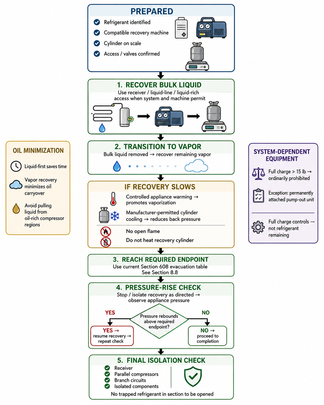
Figure 8.7.1 - General Type II liquid-first then vapor recovery sequence.
AI-generated instructional figure: It may contain visual inaccuracies. Use the accompanying lesson text and cited authoritative sources to verify technical and regulatory details.
EPA 608 Exam Focus
What Students Must Remember
- Recover accessible bulk liquid first when the system and recovery equipment permit.
- After bulk liquid is removed, recover the remaining vapor.
- Liquid recovery usually reduces recovery time.
- Vapor recovery tends to minimize oil carryover.
- A receiver can contain substantial liquid refrigerant.
- Receiver and liquid-line connections can be useful for liquid recovery.
- Do not assume every receiver port contains liquid.
- A rooftop condenser / lower evaporator arrangement can make the liquid line near the evaporator a useful liquid-rich recovery point.
- A recovery cylinder that becomes hot develops higher pressure and increases recovery-machine back pressure.
- Controlled recovery-cylinder cooling can reduce back pressure when permitted by the equipment procedure.
- Do not heat the recovery cylinder to speed recovery.
- Controlled appliance warming can promote evaporation and speed the final recovery stage.
- Do not use open flame for appliance warming.
- Refrigerant can remain dissolved in oil and can cause pressure rebound.
- After the apparent endpoint is reached, perform the appropriate pressure-rise check.
- There is no universal EPA pressure-rise hold time for every Type II appliance.
- If pressure rises above the required endpoint because refrigerant remains, continue recovery.
- Parallel compressors and isolated sections can trap refrigerant.
- A zero reading at one access point does not prove every isolated component is empty.
- Current § 82.156 prohibits ordinary system-dependent recovery equipment on appliances with a full charge greater than 15 lb, except for the permanently attached pump-out-unit case.
- The 15-lb rule is based on full charge, not the amount currently remaining.
- Exact Type II recovery/evacuation levels are covered in Section 8.8.
High-Priority Recovery Sequence
PREPARE
↓
RECOVER BULK LIQUID
↓
RECOVER REMAINING VAPOR
↓
USE CONTROLLED TEMPERATURE MANAGEMENT IF NEEDED
↓
REACH REQUIRED ENDPOINT
↓
STOP / ISOLATE
↓
PRESSURE-RISE CHECK
↓
PRESSURE REBOUNDS?
├── YES → RESUME RECOVERY → CHECK AGAIN
└── NO  → FINAL ISOLATION CHECK → COMPLETE
High-Priority Temperature Relationships
Cold appliance
→ lower refrigerant vapor pressure
→ slower final recovery
Controlled appliance warming
→ increased evaporation
→ can speed recovery
Hot recovery cylinder
→ higher cylinder pressure
→ higher back pressure
→ slower recovery
Controlled cylinder cooling
→ lower cylinder pressure
→ lower back pressure
→ can speed recovery
High-Priority Regulatory Relationship
Full charge ≤ 15 lb
→ system-dependent equipment may be possible
   subject to all other requirements
Full charge > 15 lb
→ ordinary system-dependent equipment prohibited

Exception:
permanently attached pump-out unit
Typical Exam Question Patterns
Students may be asked to:
- Identify why liquid recovery is performed first.
- Determine which access point is useful for liquid recovery.
- Determine why a receiver is important during recovery.
- Identify vapor recovery as the stage after bulk liquid removal.
- Explain why vapor recovery minimizes oil loss.
- Determine why a cold appliance slows recovery.
- Determine why a hot recovery cylinder slows recovery.
- Select controlled appliance warming as a recovery-speed aid.
- Select cylinder cooling as a way to reduce back pressure.
- Reject heating the recovery cylinder.
- Explain why pressure rises after recovery stops.
- Determine what to do after pressure rebound.
- Recognize that no universal pressure-rebound hold time applies to every system.
- Determine how an isolated parallel compressor can remain charged.
- Apply the current greater-than-15-lb full-charge limitation for system-dependent recovery equipment.
- Identify the permanently attached pump-out-unit exception.
- Distinguish the 15-lb equipment rule from the 200-lb evacuation-table threshold in Section 8.8.
High-Risk Words
Pay particular attention to:
- Liquid
- Vapor
- First
- Remaining
- Receiver
- Liquid line
- Oil
- Warm
- Cool
- Back pressure
- Rebound
- Full charge
- Remaining charge
- Greater than 15 lb
- Permanently attached
- Isolated
- Parallel
- Required endpoint
Common Mistakes and Confusing Points
Mistake 1: Recovering Vapor Only From the Beginning
Vapor recovery can minimize oil carryover, but removing accessible bulk liquid first can greatly reduce total recovery time.
Mistake 2: Assuming Every High-Side Port Is Liquid
Compressor discharge is high-side vapor.
Use a liquid-line or other verified liquid-rich access point for bulk-liquid recovery when appropriate.
Mistake 3: Assuming Every Receiver Port Contains Liquid
Receiver port behavior depends on receiver design and port location.
Mistake 4: Treating Internal Pump-Down as Complete External Recovery
Refrigerant stored in the appliance receiver is still inside the appliance.
Mistake 5: Pulling Liquid Directly From an Oil-Rich Compressor Region
This can increase oil carryover.
Use appropriate liquid-rich system access.
Mistake 6: Heating the Recovery Cylinder
Heating the receiving cylinder raises pressure and can slow recovery while increasing hazard.
Mistake 7: Using an Open Flame to Warm the Appliance
Use only controlled, permitted heat.
Mistake 8: Assuming the First Low-Pressure Reading Means Recovery Is Complete
Refrigerant can remain in oil or cold components.
Perform the appropriate pressure-rise check.
Mistake 9: Memorizing a Universal Pressure-Rise Hold Time
The project sources support the pressure-rebound concept but do not establish one universal Section 608 time for every Type II appliance.
Use the equipment/service procedure.
Mistake 10: Assuming Pressure Rebound Always Means an External Leak
During recovery, rebound commonly results from remaining refrigerant evaporating or leaving oil.
Mistake 11: Forgetting Isolated Parallel Compressors
A compressor isolated from the common headers can still contain refrigerant.
Mistake 12: Using the Amount Remaining to Apply the 15-lb Rule
The current rule uses the appliance’s full charge.
Mistake 13: Saying System-Dependent Equipment Is Prohibited at Exactly 15 lb
The current rule states:
more than 15 lb
So the prohibition threshold is:
full charge > 15 lb
not:
full charge ≥ 15 lb
Mistake 14: Forgetting the Pump-Out-Unit Exception
The exception is for system-dependent equipment permanently attached to the appliance as a pump-out unit.
Mistake 15: Mixing the 15-lb and 200-lb Rules
15 lb
→ system-dependent recovery-equipment limitation
200 lb
→ Type II evacuation-table classification
They answer different questions.
Concept-Check Questions
Question 8.7-1
Why is accessible bulk liquid normally recovered before the remaining vapor when the appliance and recovery machine permit?
A. Liquid recovery usually moves refrigerant mass faster and can reduce total recovery time.
B. Vapor refrigerant is illegal to recover.
C. Liquid recovery automatically reclaims the refrigerant.
D. Liquid recovery eliminates the need to reach the required recovery endpoint.
Question 8.7-2
Which statement best describes the effect of a hot recovery cylinder?
A. It lowers cylinder pressure and always speeds recovery.
B. It raises cylinder pressure and can increase recovery-machine discharge back pressure.
C. It converts vapor into lubricating oil.
D. It increases the cylinder’s allowable fill weight.
Question 8.7-3
Near the end of recovery, why can controlled warming of the appliance help?
A. It can promote evaporation of remaining refrigerant and raise appliance vapor pressure.
B. It permanently changes the refrigerant into a noncondensable gas.
C. It allows the recovery cylinder to be overfilled.
D. It eliminates the need for a recovery machine.
Question 8.7-4
The recovery machine reaches the required endpoint, but appliance pressure rises again after the machine is isolated. What is the most likely Type II recovery interpretation?
A. Refrigerant may still be evaporating from cold components or leaving system oil, so additional recovery may be needed.
B. The recovery cylinder has automatically become empty.
C. The pressure rise proves that the refrigerant has been reclaimed.
D. The technician should open the appliance immediately.
Question 8.7-5
A supermarket rack uses several compressors in parallel. One compressor is isolated by suction and discharge valves. Which statement is correct?
A. The isolated compressor is automatically refrigerant-free.
B. The isolated compressor can still contain refrigerant and must be properly recovered before it is opened.
C. Parallel compressors cannot be isolated.
D. The common suction pressure proves the isolated compressor is empty.
Question 8.7-6
An appliance has a full charge of 22 lb but only 9 lb remain because of a leak. May ordinary portable system-dependent recovery equipment be used solely because less than 15 lb remain?
A. Yes, because only the amount remaining controls.
B. Yes, if the recovery cylinder is cooled.
C. No, because the current limitation is based on the appliance’s full charge.
D. No, because system-dependent equipment is prohibited on every appliance regardless of charge.
Question 8.7-7
What is the current specific exception to the ordinary prohibition on system-dependent recovery equipment for an appliance with a full charge greater than 15 lb?
A. The refrigerant is recovered as vapor only.
B. The recovery cylinder has two valves.
C. The system-dependent equipment is permanently attached to the appliance as a pump-out unit.
D. The appliance is located outdoors.
Question 8.7-8
Which sequence best represents the general Type II recovery procedure taught in this section?
A. Heat recovery cylinder → vent vapor → recover liquid → open appliance.
B. Recover bulk liquid → recover remaining vapor → reach required endpoint → perform pressure-rise check → recover more if needed.
C. Recover vapor only → stop when flow slows → assume all isolated sections are empty.
D. Evacuate with a vacuum pump first → identify refrigerant afterward → recover into disposable cylinder.
Answers and detailed explanations will be provided in
8.15 - Answers and Explanations.md.
Section Summary
The basic Type II recovery sequence is:
prepare
→ recover accessible bulk liquid
→ recover remaining vapor
→ manage temperature if needed
→ reach required endpoint
→ perform pressure-rise check
→ recover additional refrigerant if pressure rebounds
→ verify isolated sections
→ complete recovery
Important practical relationships are:
Liquid-first recovery
→ faster bulk mass removal
Vapor recovery
→ slower
→ useful for completion
→ tends to minimize oil carryover
Controlled appliance warming
→ promotes vaporization
Controlled cylinder cooling
→ reduces receiving pressure / back pressure
Hot recovery cylinder
→ higher back pressure
→ slower recovery
Refrigerant dissolved in oil
→ can leave oil after recovery stops
→ pressure rebound
→ additional recovery may be required
For large commercial systems:
parallel compressors / receivers / branch circuits
→ check isolation carefully
→ do not assume one gauge proves every section is empty
The current system-dependent recovery-equipment rule is:
full charge > 15 lb
→ ordinary system-dependent equipment prohibited
with the specific exception:
permanently attached pump-out unit
The exact Type II recovery/evacuation endpoints are covered next in:
Section 8.8 - Type II Evacuation Requirements.
References
Current EPA and Regulatory Sources
-
Electronic Code of Federal Regulations, 40 CFR § 82.156 - Proper Evacuation of Refrigerant From Appliances, verified August 12, 2026.
-
U.S. Environmental Protection Agency, Section 608 Test Topics, verified August 12, 2026.
-
U.S. Environmental Protection Agency, Stationary Refrigeration Service Practice Requirements, verified August 12, 2026.
-
U.S. Environmental Protection Agency, Refrigerant Recovery and Recycling Equipment Certification, verified August 12, 2026.
-
U.S. Environmental Protection Agency, Recovering, Recycling, and Reclaiming of Refrigerants, verified August 12, 2026.